
Brighter Gameboy
My son now owns a Gameboy Advance. Nothing special since obviously everybody all over the world got one ;-)
And like nearly everybody all over the world who owns a GBA, I began to complain about the rather bad screen
(expressed in terms of visibility in darker or lets say not so bright environments, likely to be found in living rooms or other enclosed locations where one may find oneself in the mood of playing with the Gameboy). My son claims the opposite, but he fondly uses the lighting add on I bought, when he plays in dim locations.
The add-on is named "Power Shield Advance", type SV-5821 from InterAct and is sold at Toys-R-Us over here in Germany. It is powered from the link port, features an on-off switch and a dimmer. The link port is fed through, altogether a very nice device.
The main drawback is the current the device draws from the link port: 100 mA if the dimmer is adjusted to full brightness. Keeping in mind the power consumption of the Gameboy itself, another 120 to 130 mA, one can see, that is no solution. At least not a good one.
Clearly to be seen, that this has to be changed...
The alternative to the power eating incandescent lamp is a white LED, consuming about 20 mA and still beeing brighter than the incandescent lamp. There are 5 mm types available which make it advisable to not look directly into the "beam", to prevent seeing "blue spots" afterwards. So keep caution !
Some time ago I upgraded a small key ring type flashlight with a white LED, recycling a worn out 12 V garage door transmitter battery. Adding a shunt resistor finished the deal. A little mathematics, 12 V from the battery minus 3.6 V for the LED at 5 mA gives somewhere around 1.6 kΩ, and there we go. I designed for 5 mA because the old battery was not able to deliver significantly more than that. This thingy now works since over two years, not beeing too much in use I confess.
Some day this summer I read an announcement from Zetex, describing a step up switch mode converter IC especially designed for making white LED flashlights :-)
The IC comes in a 5 pin SMD housing and together with a transistor, a diode, a resistor, a coil and a capacitor, all as SMD types, one can build a high performance LED flashlight powered from a single battery cell. IC, transistor and diode are Zetex parts, coil, resistor and capacitor are off the shelf parts. Almost. It is very hard to find sub Ω resistors in SMD since most parts of that sort are the rugged ones, capable of dissipating 5 watts upwards. The coil recommended by Zetex should have 100 µH and a serial resistance of 500 mΩ or less ... another challenge to find as well.
 I contacted Zetex to get the
address of a dealer in Germany where I could order their devices, but without success (no dealer available for quantity one). I want to express many thanks to the Zetex guys (and girls ;-) who are
found to be very cooperative when I explained the goal of my inquiry, the illumination of my sons Gameboy. Some weeks after the first contact I received an
evaluation board readily built with LED and fixture for an AA-type battery as well as the Zetex parts for the Gameboy light.
I contacted Zetex to get the
address of a dealer in Germany where I could order their devices, but without success (no dealer available for quantity one). I want to express many thanks to the Zetex guys (and girls ;-) who are
found to be very cooperative when I explained the goal of my inquiry, the illumination of my sons Gameboy. Some weeks after the first contact I received an
evaluation board readily built with LED and fixture for an AA-type battery as well as the Zetex parts for the Gameboy light.
Thanks go to you, Margot and George !
In the meantime I did some research on different LEDs. Good advice on that subject can be found at www.gbalight.com. The subtitle of that page “Devoted to the quest for the perfect light” speaks for itself :-)) The author made tons of experiments and investigations concerning white LEDs and their usability for lighting the GBA. Admittedly all experiments on that page (and many news I read) only deal with the 5 mm types of white LEDs. Those LEDs obtainable here in Germany have a very narrow focus of around 22 degree, making an evenly illumination of the GBA screen rather impossible, due to the short distance between LED and screen imposed by the Power Shields dimensions. So I focused on the less bright 3 mm types having a focus of around 45 degree, and use two of them.
 As prototype fixture for the LEDs I
built a wire frame which I mounted to the GBA via two modified computers motherboard spacers which fit neatly into the holes on the rear of the GBA.
As prototype fixture for the LEDs I
built a wire frame which I mounted to the GBA via two modified computers motherboard spacers which fit neatly into the holes on the rear of the GBA.
Easily to be seen that this setup is much too fragile to be used as permanent solution.
First I connected the two LEDs in parallel and powered them directly from the batteries since I didn´t know whether the link port can deliver the current of 40 mA. Now I know, it can :-)
Depending on the low voltage of the batteries (max. 2.6 V with freshly charged batteries) the two LEDs did no good job in lighting the screen, but I could prove my theory, that two
not so bright LEDs are able to evenly illuminate the GBA screen.
In the next step I built a circuit with the Zetex parts to do some measuring with different
resistors and coils. I used one side copper plated breadboard material and tried to grind away all what prevented the copper from building the correct connections between the pins
, using an electrical one hand grinding tool (Dremel or Proxxon alike). With moderate success, since the tool was too big, I worked free hands and those SMD pins are very
small ... but finally it worked, I managed to fit the 4 parts onto the board and started my measurements.
With a sense resistor of 0.22 Ω and a 10 µH / 1.8 Ω serial resistance coil the circuit draws
60 mA at 5 V supply voltage (with a GBC game) and about 40 mA at 3.3 V (with a GBA game inserted into the GBA cart slot). Using a sense resistor of 1.3 Ω and a 100 µH coil I
get 15 mA at 3.3 V and 22 mA at 5 V :-)) Sounds good. Using 3 mm LEDs in the same setup gives similar currents.
Next I will try to shrink the layout of the board so it will fit into the housing of the Power
Shield, the original board still in place. I want to keep it since I want to use the switch and the pass through for the link port. The dimmer will not work but what the heck, we want a brighter Gameboy :-)
To ease the job of layouting I used EAGLE. I had troubles trying to convince the router of EAGLE to connect those SMD pads to the traces, but that may or may not depend on my incompetence :-) Don´t bother with some very short connections lying within whole copper plated areas. They only deal with connecting the SMD pads logically as well. Layout and design in EAGLE format are obtainable for download.
 This time I used a drilling machine
with milling cutter and a x-y-axis sled (?) to craft the board.
This time I used a drilling machine
with milling cutter and a x-y-axis sled (?) to craft the board.
I think it´s well done ;-))
 The parts (left to right):
- Resistor 1,3 Ω (Reichelt, Chip-Widerstand Bauform 1206, order number SMD 1/4W 1R3)
- Coil 100 µH / 3,8 Ω (Reichelt, muRata Chip Coil, order number LQH3C 100µ)
- Transistor FMMT617 (Zetex)
- IC ZXSC300 (Zetex)
- 2 LEDs (Reichelt, Kingbright LEDs 3 mm ultra bright, order number LED 3-2000WS)
The board is 8 by 12 mm in size and fits neatly into the intended place in the housing of the Power Shield. The board is fixed to the link port connector by means of twosided adhesive band. One has to keep an eye on the distances between the board edges and the guidings for the original board on the inner surface of the housing.
 The wires from the new converter board to
ground and the power switch, respectively, have to be routed on the upper side of the board around the devices (see arrows). To keep the board as slim as possible, I used 0.5 mm thick copper plated epoxy material. The
normally found 1.5 mm thick material would have been too thick to fit into the housing ... this SMD coil is pretty big for its size ;-)
The wires from the new converter board to
ground and the power switch, respectively, have to be routed on the upper side of the board around the devices (see arrows). To keep the board as slim as possible, I used 0.5 mm thick copper plated epoxy material. The
normally found 1.5 mm thick material would have been too thick to fit into the housing ... this SMD coil is pretty big for its size ;-)
To find out which contact of the switch is the correct one to be unsoldered and moved to the converter board, one may have to use a multi meter. In my Power Shield Advance it was the middle pin of the switch. An additional wire connects the ground pad of the converter with ground of the original board.
In the first approach I wanted to maintain the original leads of the incandescent lamp to power the LEDs, so I cut them near the lamp bulb. Later I realized that this would cause too many flying soldering connections since I would have to patch the leads to reach the LEDs. So I decided to replace both wires between converter and LEDs with new ones in the correct length.
 Next thing to do was to decide
where in the Power Shields lid the LEDs should be mounted and in what direction they will beam. The routing of the leads and wires has to be considered as well. I left the LED leads in their original length and
soldered the wires to the ends, respectively. To route the wires into the old translucent lamp housing I had to cut small notches into it which work as spacers for the not isolated LED leads as well.
Next thing to do was to decide
where in the Power Shields lid the LEDs should be mounted and in what direction they will beam. The routing of the leads and wires has to be considered as well. I left the LED leads in their original length and
soldered the wires to the ends, respectively. To route the wires into the old translucent lamp housing I had to cut small notches into it which work as spacers for the not isolated LED leads as well.
After mounting the transparent cover of the lamp bay the LEDs are still not fixed, so I put a drop of hot melting adhesive at the leads directly behind the screws of the cover. The electronic housing of the Power Shield was already closed at that point, the targeting of the LEDs was executed with the GBA in place and operating the LEDs from the link port.
 The GBA with modified Power
Shield in operable state.
The GBA with modified Power
Shield in operable state.
One can see the bended leads of the LEDs. Be careful to not damage the LED body by bending too tight. Use a fine pliers and give the leads time to follow the force you apply.
 The brightness of the modified
Power Shield is sufficient to play in complete darkness (and in dim surrounding as well). Only the lower corners are not illuminated very well.
The brightness of the modified
Power Shield is sufficient to play in complete darkness (and in dim surrounding as well). Only the lower corners are not illuminated very well.
 No problems when playing with
ambient light.
No problems when playing with
ambient light.
Conclusion:
The 3 mm LEDs from Reichelt have a relativ strong blueish tint and a rectangular, nearly square spot is to be seen in the centre of the beam (not visible on the picture). It will not worry when playing a colourful game, but a perfectionist may be irritated.
The usage of two LEDs lying apart did not bring the expected result. The brightness distribution is much better than with one bright and highly focused 5 mm type of LED, but instead of having one reflection spot in the top middle of the screen, we now have two of them, lying at the left and right screen edge, respectively :-(
Hopefully the action happens midscreen :-)
Addendum
Paul, known as owner of www.gbalight.com, told me, that in his opinion Gameboy users are rarely willing to rebuild that design since etching boards and soldering are not wide spread skills.
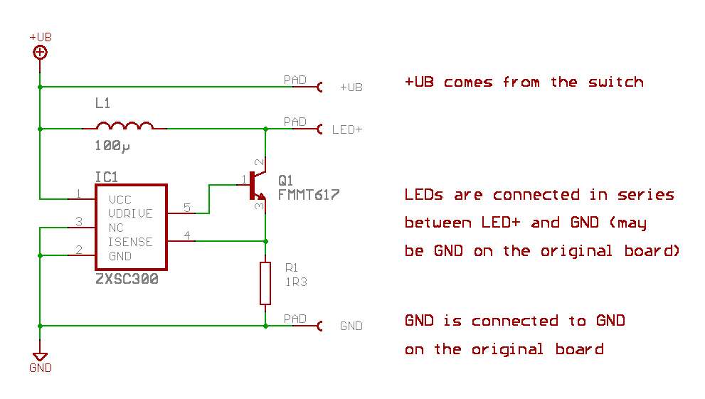
To give the hesitant of you an impression of the “complexity” of the design without having to install and learn EAGLE, I show the schematic and board layout as pictures:
 The schematic...
(in full resolution)
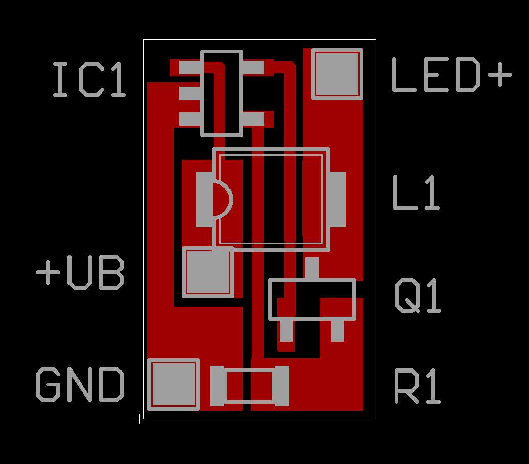
 ...and the layout.
(in full resolution)
Not really impossible, mhm... ;-))
To transfer the layout to the copper plated board I printed the layout in original size on paper and fixed the paper to the board. Then I used a stylus to pierce holes through the paper at each corner of the copper areas. Those markings gave me clues where to cut the copper to form the traces. It was not perfect, but it worked, as you can see on the photo with the parts.
One problem to report. The SMD coil was too small to get the two traces from the IC to the transistor routed underneath it using the described technique. So I had to mount it on solder “stilts” a little away from the boards surface, but it was no problem and I succeeded on the first attempt.
Addendum 2
I sat down and made another design which takes in consideration the correct dimensions of the coil I had on hands. Since the pad spacing of this SMD coil is only 1.3 mm, I had space to route two 0.4 mm wide traces underneath it. Structures this small are not feasible to be drilled with the above described procedure, so I did one step beyond and optimized the layout for size. The resulting board now is 6.8 x 12.1 mm in size (against 8.6 x 13.9 mm for the first approach). The schematic has not changed, so here you see only the new board layout.
 The complete EAGLE design again is downloadable.
Besucher seit
25.11.2000